Basic concepts
Are you eager to install Laiye Automation Platform software to automate your process?
Don't worry. Don't worry. I can't miss my firewood cutting skill when I sharpen my knife. This chapter introduces four basic concepts of Laiye Automation Platform: process, process block, command and attribute. These four concepts run through the whole article, and will be repeatedly used as basic terms in later chapters, so please keep them in mind. This chapter will not be too long. Please be patient and don't skip it easily!
Concept
Let's take a look at these four basic concepts first.
- Process
- Process block
- Command
- Attribute
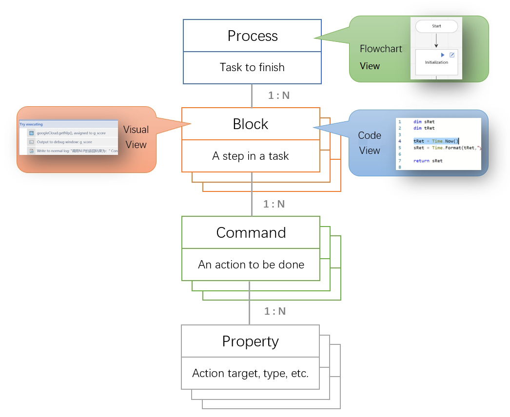
These concepts are inclusive. A process contains multiple process blocks, a process block contains multiple commands, and a command contains multiple attribute.
The first concept is: Process . The so-called process refers to a Task to be completed with Laiye Automation Platform, and a Task corresponds to a process. Although Laiye Automation Platform can be used to create multiple process one after another, only one process can be written and run at the same time. Future use Laiye Automation Worker and Laiye Automation Commander It is also used with the process as the basic unit.
Laiye Automation Platform has built-in some classic process examples. Beginners can open these process examples, try to run these process and learn by imitation. Of course, they can also create a new process themselves.
Process chart
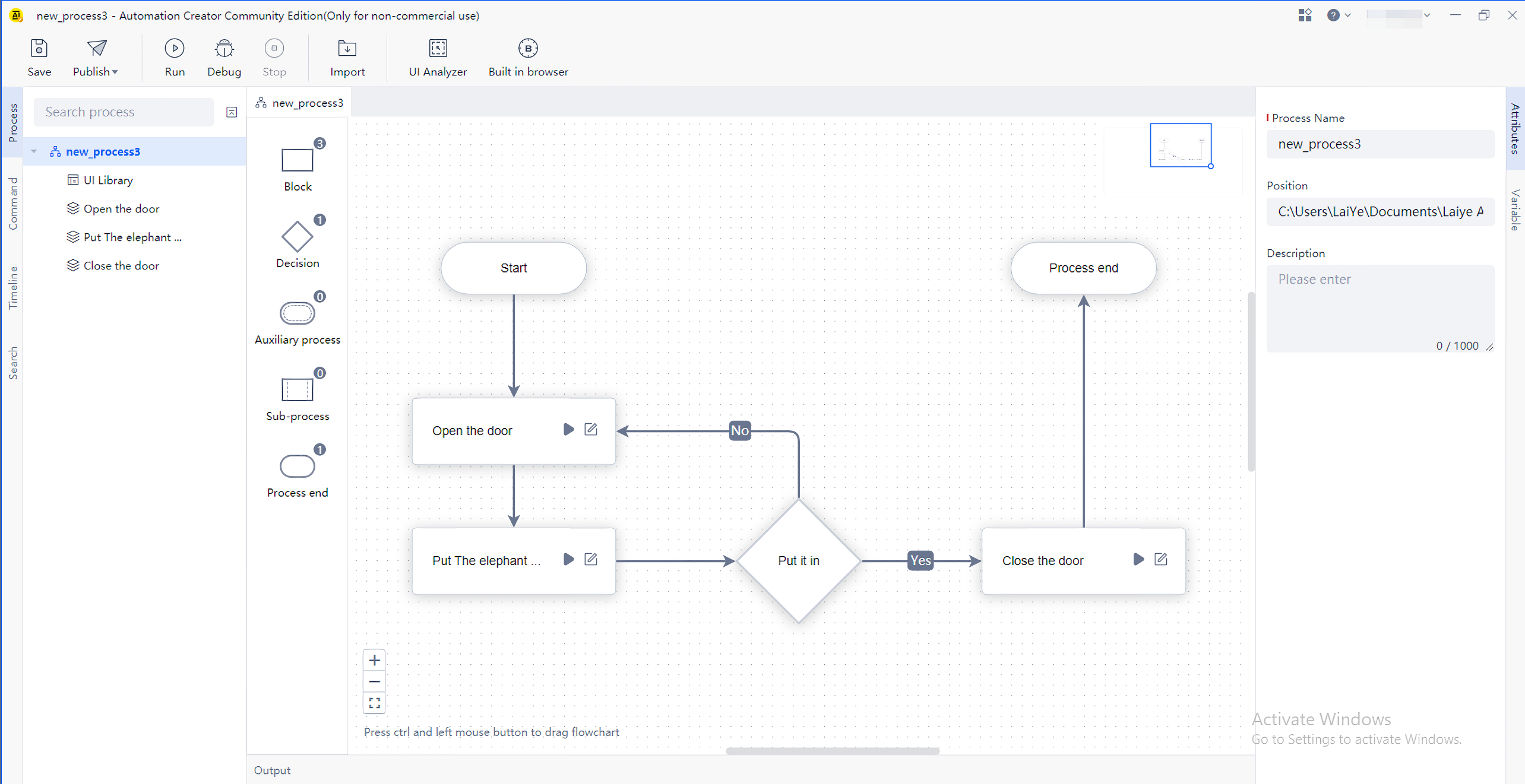
After creating or opening a process in Laiye Automation Platform, you can see that each process is represented by a process diagram.
In the process diagram, there are a series of "components", of which "start", "process block", "judgment" and "end" are the most commonly used components. For beginners, other components such as "auxiliary process" and "sub process" can be mastered first, and will be learned later.
Drag a component from the "component area" on the left to the blank "canvas" in the middle to create a new component, such as a new process block. Drag the mouse on the edge of the component on the canvas (at this time, the shape of the mouse will become a cross). You can Settings arrow connection between components.
Put multiple components on a canvas and connect them with arrows to form a process diagram. As shown in the figure below:

There must be one and only one "start" component in each process diagram. As the name implies, the process starts from here and runs to the subsequent components in turn along the arrow.
In each process diagram, there can be one or more "end" components. Once the process encounters the "end" component, it will naturally stop running. Of course, there may be no "end" component. When the process runs to a process block, and the process block has no arrow pointing to other process blocks, the process will also stop running.
In each process diagram, there may be one or more "judgment" components, or there may be no "judgment" components. During the operation of the process, the "judgment" component will make the following operation paths diverge according to certain conditions. When the condition is true, follow the "yes" arrow to run subsequent components; Otherwise, follow the "no" arrow to run subsequent components. If you are new to Laiye Automation Platform, you may not be able to use the "judgment" component for the time being. The "judgment" component will be described in detail later in this chapter.
Finally, and most importantly, in the process diagram must There are one or more "process blocks", Process block It is the second important concept to be introduced in this chapter.
We can divide a Task into several steps, and each step is described by a "process block" in Laiye Automation Platform. For example, if our Task is to "put the elephant in the refrigerator", then we can divide this Task into three steps:
- Open the refrigerator door
- Put the elephant in
- Close the refrigerator door
Each of the above steps is a process block. Of course, this example is just a joke. Laiye Automation Platform can't help us open the refrigerator door. However, it can be seen from this example that in Laiye Automation Platform, a step, or a process block, only describes the things to be done in general, and does not involve the details of how to do them for the time being.
Laiye Automation Platform does not specify how detailed a process block should be: a process block can be very coarse, and even a process can have only one process block. In this case, a process and a process block can actually be regarded as the same concept; The process block can also be very thin, and a process can be divided into many process blocks. So how many are the most appropriate? It depends on your personal preference. However, we have two suggestions: one is to put relatively independent process logic in a process block; Second, the total number of process blocks should not be too many. In a process, it is recommended not to exceed 20 process blocks.
Why do you suggest that? In fact, Laiye Automation Platform does not specify the maximum number of process blocks. If you are willing, there is no problem to put 200 or 2000 process blocks. However, the original intention of the "process chart" in Laiye Automation Platform is to enable "business experts" who design RPA process and "ordinary staff" who use RPA to communicate better. Both parties determine the general steps and divide the process blocks at the early stage of design. Then, business experts are responsible for filling in the details of each process block, and ordinary staff do not need to pay attention to these details. Obviously, at this stage, if there are too many process blocks, communication will be more difficult.
There is a "run" button on the toolbar of Laiye Automation Platform. After pressing this button, all components in the process will run in sequence starting from the "start" component. There is also a triangle shaped button on each process block. After pressing, only the current process block will run. This function makes it convenient for us to test each process block separately when developing RPA process.
There is also a button similar to "paper and pen" on each process block. After pressing it, you can view and write the specific contents of this process block. The specific writing method is completed by "visual view".
Visual view
As mentioned in the previous section, each process block also has a button similar to "paper and pen". Click this button to view and write the specific contents of this process block. The UI will also switch from "process view" to "visual view".

Laiye Automation Platform compiles the "visual view" of process blocks, and its interface is shown in the following figure:

In the figure, three main areas are marked with three red boxes. From left to right, they are command area, assembly area and attribute area.
Here we introduce a third important concept: command . The so-called command means that in a process block, Laiye Automation Platform needs to be informed of the specific actions to be taken and how to do them. Laiye Automation Platform will follow the commands we give one by one and faithfully implement them. Continuing with the previous example, if the process block is "open the refrigerator door", the specific command may be:
- Find the refrigerator door handle
- Hold the refrigerator door handle
- Open the refrigerator door
Of course, as before, this example is just an example. Laiye Automation Platform can't open the refrigerator door. Almost all commands that Laiye Automation Platform can complete are listed in the "command area" on the left, that is, the first red box in the figure above. Including simulated mouse and keyboard operations, window and browser operations, etc. the specific commands contained in each category can be further expanded and viewed.
The area contained in the second red box in the figure is called the "assembly area". We can arrange and combine commands here to form the specific content of the process block. You can add commands to the assembly area by double clicking the left mouse button or dragging them directly from the command area on the left. You can also drag commands in the assembly area to adjust their order or inclusion relationship.
Command is an action that we ask Laiye Automation Platform to do, but command alone is not enough. We need to add some details to this action. These details are the fourth concept we want to introduce: Attribute . If the command is just a verb, then the attribute is the noun, adverb, etc. related to this verb. When they are combined together, Laiye Automation Platform will know how to do this action.
Let's also use the above example. For the command "open the refrigerator door", its attribute include:
- How much strength
- Left hand or right hand
- How far apart
When writing a process block, just click a command with the left mouse button in the "assembly area" to highlight it. The attribute of the current command can be displayed in the attribute variable area on the right. The attribute includes "required" and "optional". Generally speaking, Laiye Automation Platform will automatically Settings the default value of each attribute for you, but please pay attention to the "required" attribute, which may often need to be modified as needed. For the "optional" attribute, it is generally better to keep the default value, and only modify it when there are special needs.
The display mode of the assembly area you see now is called "visual view". In this view, the order and inclusion relationship of all commands are displayed in the form of block stacking, and some details are appropriately hidden, which is easier to understand. "Visual view" reflects the important feature of "simplicity" of Laiye Automation Platform as an RPA platform. Therefore, designers of Laiye Automation Platform have seriously considered and collided with each other in the expression, detail and aesthetics of "visual view", and reached a relatively balanced state. Even novices without any programming experience can roughly grasp the logic when they see the "visual view".
Arranging the command area, assembly area and attribute area from left to right is the default arrangement of Laiye Automation Platform. You can also drag the property on each area to adjust them to the arrangement you like.
Source view
You may have noticed that on the assembly area, there is a switch that can be toggled left and right. The options on the left and right sides are "visualization" and "source code", and the default is "visualization". We can switch it to the "source code" state. At this time, the attribute variable area will disappear and the assembly area will become as shown in the following figure:

The assembly area displayed in this way is called "source code view". Similar to the visual view, the source code view actually shows the commands contained in the current process block and the attribute of each command. However, there is no box to identify each command, and there is no attribute area to list each attribute neatly, but All are displayed in the form of program code.
If you are familiar with Laiye Automation Platform, you can switch to the source view and write commands and attribute without leaving the keyboard. Laiye Automation Platform optimizes the source code view in terms of experience. It can help you quickly select the commands you need, fill in various attribute, and let you write commands one by one in a happy mood.

Both the visual view and the source code view describe the same process block. They are actually two different ways of presenting the same thing, with the same connotation. The visual view highlights each command and their relationship in a graphical manner, which is suitable for showing the overall logic of process blocks; The source code view highlights the essence of process blocks in the form of program code, and fully shows all the details.

For example, the visual view and the source code view are just like the view of the plane above. In fact, the left and right wings of this F-16 aircraft are basically symmetrical, but why do they look different? Because its right wing is painted with exterior view to show the overall shape, and its left wing is painted with perspective view to show the internal structure. The same plane can show different contents in two views, so as to take into account the concerns of different audiences. By the same token, only when the same process block shows different contents in two views can the two indicators of "simplicity" and "quickness" of RPA platform be taken into account.
Some readers may ask, should I use visual view or source code view to develop RPA process? In fact, you don't have to worry about this, because no matter which view you use, you can at any time Switch to another view. No matter what you write in one view, after switching to another view, these contents will All Keep it and show it in another view, and vice versa. Therefore, you can use the visual view first. After getting familiar with it a little, you can switch to the source view to taste it and understand the internal principle. If you still have difficulties for the time being, you can switch back to the visual view. I have no phobia of choice! This is also the strength of Laiye Automation Platform!
In addition, the source view has another advantage when you are in the Forum When asking for help from others, just switch to the source view, copy and paste the source code, and your process block can be displayed in text. The other party can read the source code directly, or paste the text of the source code into their own Laiye Automation Platform, and switch to the visual view. In this way, the efficiency of communication will be greatly improved.
The programming language used in the source code view is the BotScript language developed by Laiye Automation Platform. The specific language features will be described in detail later.
Summary
In this chapter, we learned four important concepts: process, process block, command and attribute. A process contains multiple process blocks, a process block contains multiple commands, and a command contains multiple attribute. We also saw three views: process view, visualization view and source code view. The process view is the presentation of the process, and the visualization view and the source code view are the presentation of the process block. The relationship between them is shown in the following figure:
Advanced content
This section is an advanced content. Please read this section when you need to share and transfer data among multiple process blocks and use the "judgment" component in the process diagram. If you are a beginner of Laiye Automation Platform, you can skip it.
Process variables
"Variables" can be used to store data in process diagrams and process blocks: variables in process blocks can only be used in current process blocks, and cannot be directly used in process diagrams and other process blocks; If a variable is defined in the process diagram, it can be directly used in all the process blocks included in the process diagram.
Below, we will illustrate the specific usage of process diagram variables.
Suppose there is a process diagram containing two process blocks, named "process block 1" and "process block 2", as shown in the following figure. "Process block 1" runs first. Its function is to obtain the current system time and convert the system time into string format. It runs after "process block 2". Its function is to display the system time in string format generated by "process block 1" in the form of debugging information.
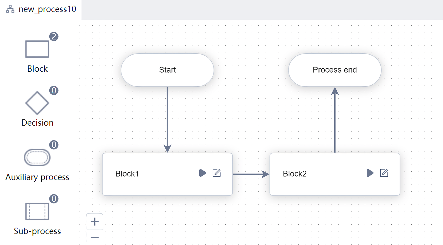
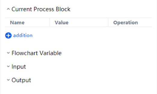
Since "system time in string format" needs to be transferred between "process block 1" and "process block 2", it can be saved in process diagram variables for transfer. We first define this variable in the process diagram. In the "process chart" view, find and click the "variable" property on the right to see all process chart variables. Click the "add" button and enter the variable name x (case insensitive), you can add a process diagram variable.
Each process diagram variable can also specify "use direction", including "input", "output" and "None". Among them, "input" and "output" are high-level functions that are only needed in sub process. If we only consider the current process, it is better to set the use direction to "None".
Click the "paper and pen" icon of process block 1 to enter the visual view of process block 1, insert a command of "get the current time of the machine" and a command of "get the time text in the specified format" (under the "time" Category), and set the "time" attribute in "get the time text in the specified format" to the result of "get the system time", It is saved in the process diagram variable in an easy to read string format x Middle. because x It is a variable of process diagram, so it can be used directly in the next process block x Value of.

If you think it is too troublesome to enter the variable name, or the variable name is too long to remember. In the "attribute" area of the "visual view" of the process block, you can also find a fx After pressing the button or drop-down button, a menu will pop up listing all available process block variables, process diagram variables and system variables. Click to select. As mentioned above, "process block variable" is only used in the current process block. "Process diagram variable" can be used in any process block of the whole process diagram. In addition, there is "system variable", which you do not need to define or assign. You can directly use the preset value in it.
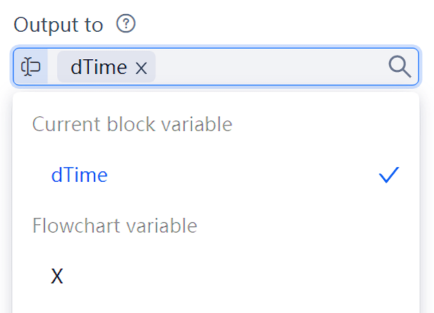
Next, click the "paper and pen" icon to enter process block 2, insert a "output debugging information" command, and set the "output content" attribute to x (as previously described, variables x It is a variable of process diagram and can be used directly without redefinition).

Return to the UI of the process diagram, and then click the "run" button to see the running results and display the current time.
Input and output of process block
The previous section showed how to transfer data between two process blocks using process diagram variables. This method is simple and easy to understand, but it is a little troublesome: it is obviously the transfer of data between two process blocks, and it seems superfluous to involve the process diagram. In fact, data can be transferred between two adjacent process blocks without relying on process diagram variables. At the end of the operation of the previous process block, a value can be "output", and this output value is directly "transmitted" to the next process block through the arrow connecting the two process blocks.
Then, how to output a value in the previous process block and obtain this value in the next process block?
Very simple. First, go to the previous process block, find the "Jump Out and Return" command under "lexical grammar" in the "command area", drag it to the "assembly area", and Settings its output value in the "attribute area", which can be numeric value, string, variable or expression. Or, if you are used to using the source view, write in the process Return <Output Value> , The effect is the same. When running, if this command is encountered, it will jump out of the current process block and pass the output value to the next process block.
Next, enter the next process block. When a command needs to use the output value of the previous process block (that is, the input of the current process block), directly find the corresponding attribute in the "attribute area" and click the letter marked on the right fx And select "input of process block" in "system variables" in the pop-up menu (as shown in the figure below), so that this value can be obtained automatically during operation. Of course, if you are used to using the source view, you can also write directly $BlockInput (before the variable $ The symbol indicates that this is a system variable).
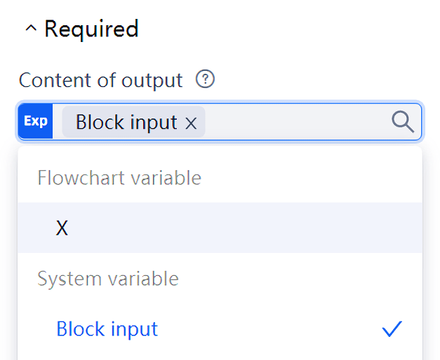
Next, we will still use the examples in the previous section to illustrate the specific methods of direct output and input between process blocks.
First, enter "process block 1", whose function is to obtain the current system time and convert the system time into string format. Assuming that the converted result is saved in the variable sret, all you need to do is drag a "Jump Out and Return" command and take sret as its output value. Here's another trick: when the command "get the time text in the specified format" is adjacent to the command "Jump Out and Return", you don't even need the variable sret. Just press in the attribute of "Jump Out and Return" fx Button, and select the system variable "result of the previous command", so that a variable can be omitted and the effect is the same.
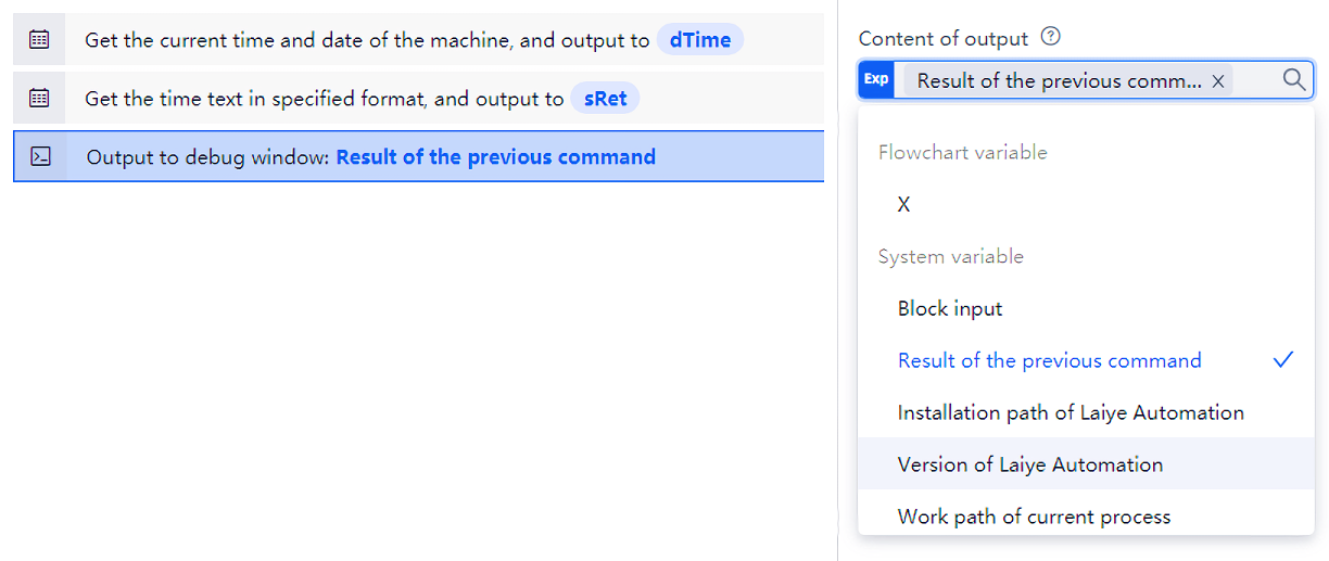
Then enter "process block 2", insert a "output debugging information" command, and set the "output content" attribute as the system variable "input of process block". Running the whole process chart, we can see that the expected results have also been obtained. Of course, you can't just run process block 2 here, otherwise, the result will be incorrect due to the lack of output from process block 1.
The use of process diagram variables or the use of output and input between process blocks are two ways to transfer data between process blocks. The former is more intuitive to use, and when the arrow between process blocks changes, it will not affect the value of process diagram variables. The latter relies on two process blocks adjacent in order, which is logically clearer. Which way to use depends on the habits of the readers.
Implementation of complex process diagram
Some people may wonder that Laiye Automation Platform only provides four components, "start", "process block", "select" and "end". Among them, "start" and "end" are not real business process components. Can they be competent for complex process diagrams only through the two components, "process block" and "select"? Just like the following figure:

Don't underestimate these components of Laiye Automation Platform. No matter how complex the process diagram is, it can also be realized through the simple arrangement and combination of these four components!
Let's look at the essence through the phenomenon: complex process diagrams can be Category according to their structural composition, which can be roughly divided into three types: sequential structure, selection structure and Loop Structure. Let's see how these three types of process diagrams can be implemented with Laiye Automation Platform.
Sequential structure
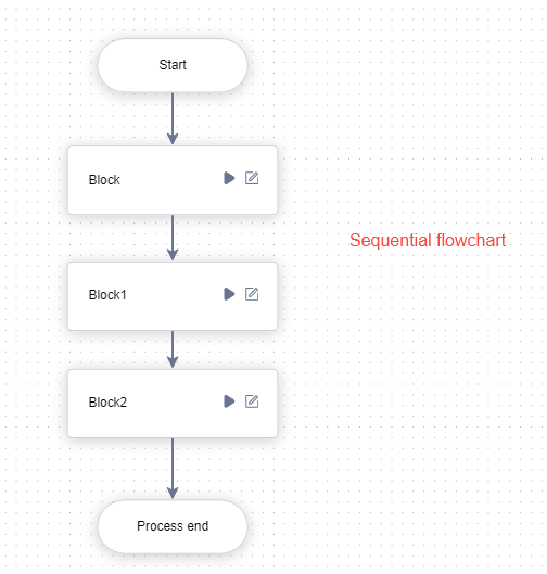
In the sequential structure, each step is executed in sequence, which is the simplest basic structure. As shown in the figure, a, B and C are three consecutive steps, which are executed in sequence, that is, the next action can be executed only after the operation specified in the previous box is completed.
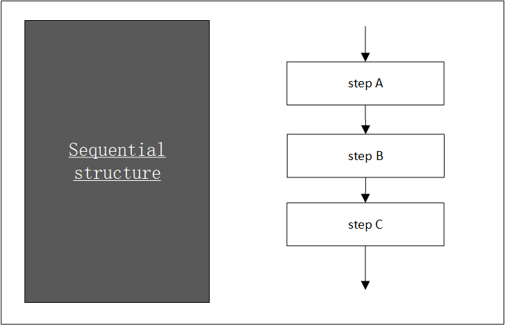
The sequence process chart of implementing sequence structure in Laiye Automation Platform is shown in the figure.
Select structure
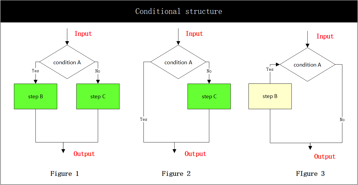
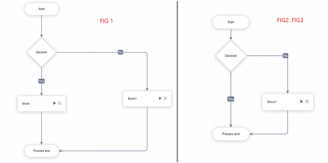
The selection structure is also called branch structure. The selection structure judges the result according to certain conditions and controls the process of the program according to the judgment result. In practical application, a branch route can be empty (as shown in Figure 2 and figure 3).
The selection process chart of the implementation selection structure in Laiye Automation Platform is shown in the figure.
Loop Structure
Loop Structure, also known as repetition structure, refers to the process structure in which a process repeatedly performs an operation under certain conditions. Loop Structure can be divided into While Structure and Until Structure.
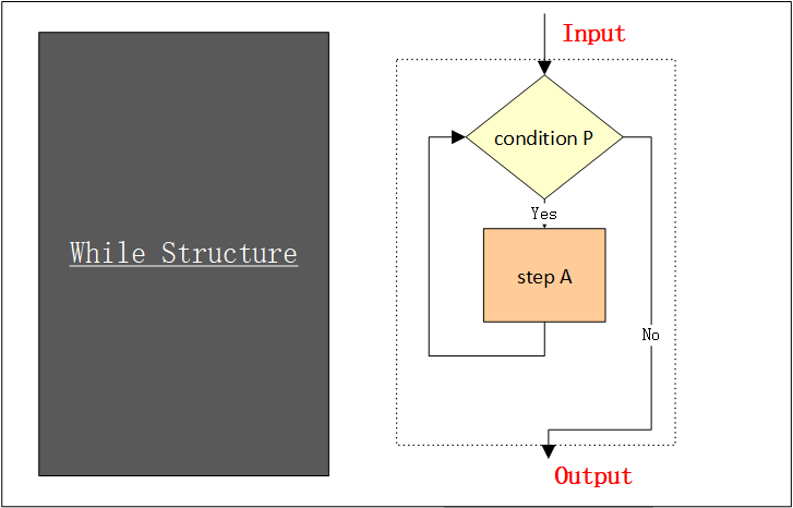
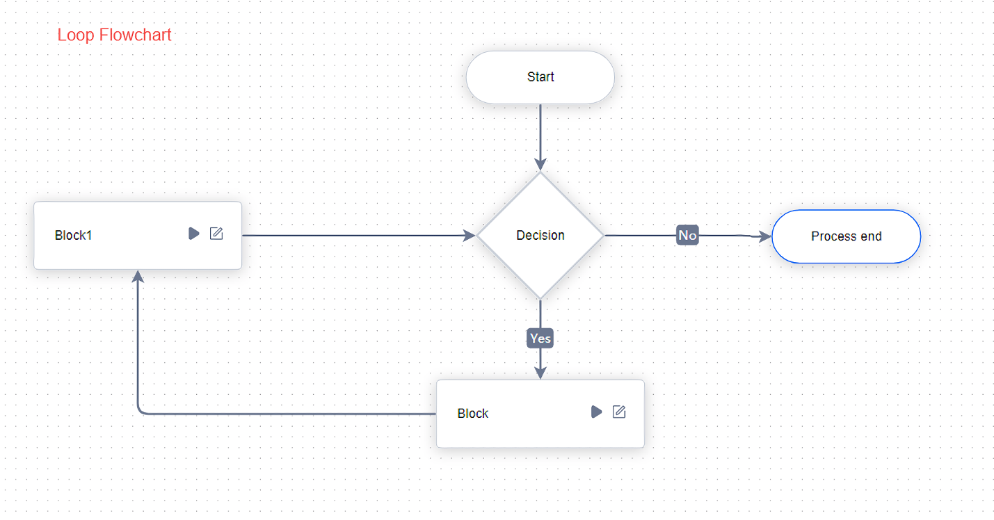
The Loop Structure can be seen as a combination of a condition judgment and a turning back. When represented by a process chart, the conditions are written in the judgment box. The two exits correspond to the execution paths when the conditions are established and not established, and one of the paths needs to return to the condition judgment itself.
While Structure : First, judge whether the given condition P is satisfied, and if P is satisfied, execute a (step); And then determines whether the condition P is satisfied; If P holds, a is executed again. If this is repeated until a certain condition P does not hold. The process ends.
Until Structure : Execute a first, and then judge whether the given condition P is true. If P is not true, execute a again, and repeat until P is true, and the cycle ends.
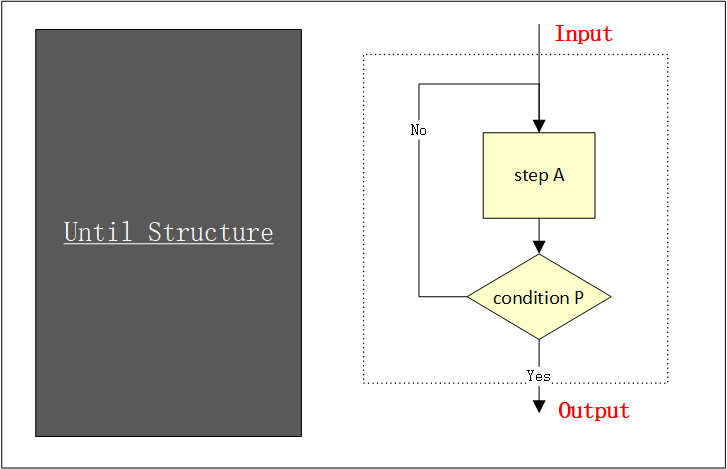
The circulation process chart of realizing the circulation structure in Laiye Automation Platform is shown in the figure.
In terms of specific use, Laiye Automation Platform uses the "judgment" component to realize the above functions. Drag the "judgment" component into the process diagram and select it with the left mouse button. You can see the attribute of the component in the attribute bar. As shown in the figure. The column "conditional expression" is very important. You can fill in a variable or expression (only process chart variables can be used here). When the process runs to this judgment, it will decide whether to continue to run along the arrow indicated by "yes" or along the arrow indicated by "no" according to whether the value of this variable or expression is true.
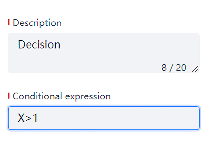
The "judge" component has two outgoing arrows, one marked with "yes" and the other marked with "no". When the "condition expression" in its attribute is true, it will run back along the "yes" arrow; otherwise, it will run back along the "no" arrow. As shown in the figure.
